Monday, 29 February 2016

Controlling blinking speed of an LED with Arduino & potentiometer


Hello friends,
In this tutorial, I will show you how to control blinking speed of an LED using Arduino Nano & a variable resistor or a potentiometer aka the pot (short form of potentiometer).

This tutorial is similar to an LED blink code but, we added a pot to it, you may think that what is pot, basically pot is a type of resistor which value can be changed. It has three legs, 1 leg on each side which are rigid and are connected to each other with the small layer of conductor & 1 is in center which is movable means we can rotate it & it has a small pin which floats on this thin layer. For example, we connect GND to one leg & 5V to another leg, Now when we rotate the center pin to GND leg, the voltage passing through center will decrease & when we rotate it to 5V, the voltage passing through center pin will increase & if we rotate it to center the voltage will be half of the 5V, means 2.5V. understand !!

Now get back to our tutorial,

Things we will need :
  1. A Arduino board ( I took Nano).
  2. A LED
  3. A resister ( 150 ohm )
  4. A potentiometer ( yes, pot )

Step 1 : Wiring


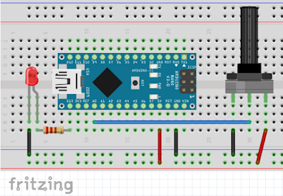
Firstly, place the Nano,  an LED & resistor on the bread board.
  1. Now, connect the Nano's 5V & GND to breadboard's power lines. 
  2. Connect one end of resistor to Nano's D13 pin & other end to an LED's anode pin or say long leg.
  3. connect cathode or short leg to the GND.


Now place the pot on breadboard.
  1. First leg of pot to GND.
  2. second to Nano's analog pin A0 &
  3. third to 5V.
Our wiring is now let's move to coding part.

Step 2 : Coding


Connect Nona to PC through the USB cable & open Arduino IDE.
Now go to  File > Examples > Analog > AnalogInput. A sketch will open, upload it to the Nano.

when uploading is done, you can change the blinking speed of an LED with the pot.


Video tutorial : 


How the code works.


You may remember, in an LED code, we took 1000 ms as delay between HIGH & LOW, means an LED remains 1 second HIGH &  1 second LOW. In this example, Arduino takes the voltage form the center leg of pot & converts it to digital form (0 - 5 to 0 - 1023). So, when we rotate the nob of the pot to 0V, we are actually decrease the time between HIGH & LOW & when we rotate the nob of the pot to 5V, we are actually increase the time between HIGH & LOW. Simple but effective way to control blinking speed of an LED.

Sunday, 28 February 2016

Blinking LED with Arduino Nano

Hello friends,
Seeing a blinking LED is so much fun, but when you make one like that by yourself then the fun is even more. ^_^

So, let the fun begin,

In this tutorial, I have shown below how to blink an LED with Arduino Nano.

Note: Using an LED without a resistor will blow led.
Things you will need.
  1. Arduino Nano
  2. A breadboard
  3. A LED ( I used 3V at 20mA led)
  4. A resistor 100 ohm

Step 1: Wiring.


You have to attach the LED to the Nano just done in the above image.

  • Connect LED's positive end to the one end of the resistor
  • Another end to Nano's digital pin 13
  • Negative end to Nano's ground.

To power the Nano board, you can use a USB cable or you can also connect an external power supply by connecting the positive pin to VIN and negative to the ground.


Step 2 : Coding


// the setup function runs once when you press reset or power the board
void setup() {  // initialize digital pin 13 as an output.  pinMode(13, OUTPUT); } // the loop function runs over and over again forever void loop() {  digitalWrite(13, HIGH);   // turn the LED on (HIGH is the voltage level)  delay(1000);              // wait for a second  digitalWrite(13, LOW);    // turn the LED off by making the voltage LOW  delay(1000);              // wait for a second } 
 
 Coding for blinking LED is so simple.
  • Just connect Nano to PC.
  • Open Arduino IDE software.
  • Go to File > Examples > Basics > Blink.
  • And upload it to the Nano board.
  • In no time, the LED should be Blink. 
  • 1 second On, 1 second OFF.

If you have any questions you can ask me in the comment section below. ^_^ 

Program Arduino Nano via Uno with ICSP


Hello Friends,

            In this tutorial, I have shown that how can you program Nano via Uno. As you can see in the above image, my Arduino Nano's USB female pin is broken. So I have to find a way to upload the sketch to it some way. One day I was Google-ing, I have read somewhere that an Arduino board can also be programmed via another Arduino board. 


Tools you will Need :

  1. Arduino Uno ( which will act as a programmer ).
  2. Arduino Nano ( to be programmed ).
  3. Jumper Cables ( Some male-male, male to female )
  4. Breadboard


Step 1: Preparing programmer

             Attach your Arduino Uno to PC. & go to File > Examples > ArduinoISP > ArduinoISP

A sketch will open, upload it on Uno. When uploading is done. unplug it from the PC. Now, Attach Uno & the board you want to program with jumper cables just like the image below.


In the above image, you can see a small (1) or (*) or (.) is marked near the ICSP headers, that is the 1st pin of ICSP headers.

  • D13 to SCK, 
  • D12 to MISO, 
  • D11 to MOSI, 
  • D10 to RST, 
  • 5V to VIN
  • GND to GND

Note: If your board's operating voltage is 3.3V then use 3.3V instead of 5V.


Step 2: Preparing Arduino IDE

                
            All wiring is done. now we have to do some settings in IDE.

  • Go to Tools > Board & select Arduino Nano.
  • In Processor, select ATmega328.
  • & In Programmer, select Arduino as ISP. ("Arduino as ISP" not "ArduinoISP")
The settings is done.
  • Now, open up the sketch you want to upload on your Nano,
  • In Menu, go to Sketch & click on "Upload using Programmer"
IDE will compile the sketch & upload it to your Nano. The RX TX LEDs will blink rapidly on both boards, & you will see done uploading.

If not, then recheck all the wiring & settings.

If you get any problems or you want to give me suggestions, you can write in the comment section below.
Happy Programming ^_^


Thank You.

Thursday, 25 February 2016

Program Arduino Uno in C Language


Hello friends,
In this tutorial, i have shown how to program Arduino Uno in C language. Arduino uses its own language to program Arduino boards, because it is easy to code & understand. But Arduino boards can also be programmed in C language.
This tutorial is for beginners who are just thinking to program Arduino Uno in C language. (I am a beginner too ;P )

So let's get started.

Step 1: Setting up things..


To write code in C, we need a software, you can use AVR studio & any other coding software. Here we will use code blocks.


It is light weight, easy to use & it has a built in software to directly upload code to your Arduino. you can download it here. 

When download is done, open it & select new project.
A dialogue box will open.
  • Select AVR project, (Yes, there is a Arduino project too, because code blocks also support Arduino programming language too. )
  • Click Go,
  • Click Next
  • Give the name of the project, (you can also change the destination folder for saving this project.)
  • Click Next.
  • It will ask for the compiler, default compiler is already selected,
  • Click Next
  • Here you have to select chip of your Arduino, ( i am using Uno, so i will select Atmega328p.)
  • Click finish.
  • A blank screen open. On the left side. There is work space
  • Double click on sources & select main.c.
 

Step 2: Writing code.


Copy or type this code there. ( you should prefer type, so you can improve your typing and coding skills.

#include <avr/io.h> // header file file for input output pins
#include <util/delay.h> // header file for delay.

int main (void)
 {
  /* set pin 5 of PORTB for output*/
  DDRB |= _BV(DDB5);

  while(1) 
  {
    /* set pin 5 high to turn led on */
    PORTB |= _BV(PORTB5);
    _delay_ms(1000); //delay 1 second

    /* set pin 5 low to turn led off */
    PORTB &= ~_BV(PORTB5);
    _delay_ms(1000); //delay 1 second.
  }
 } 
 
Understanding of some code.
  • <avr/io.h>         : To tell the chip where all the ports & pins are located.
  • <util/delay.h>   : To use built in delay features. for accurate delay.
  • DDRB               : Data direction register for port B.
  • PORTB5           : In Uno, PORTB5 is connected to digital pin 13.
  • BV                     : Bit value.


Now Click on the Gear like icon located below the menu bar. it will compile & build all the necessary files. Now go to Tools in menu bar & Click on Arduino Builder.

Step 3: Uploading Code to Arduino


A Arduino Builder program will open. Now attach the Uno to PC.
  • Click on Load sketch / hex file & browse the hex file from where you had stored it. ( default is in C drive/file_name/bin/debug/ )
  • Select board type as Arduino Uno
  • Dont change Clock.
  • Select the COM port of Uno.
  • As soon as you click on COM port, the Arduino Builder will start to program it.
  • When programming is done, L led on Uno should blink.
  • If not, then do the step 3 again.
Note : I have used Uno in this tutorial, but you can use any arduino, you just have to know which pin of IC is connected to which digital or analog pin of Arduino. 

If you any suggestions or you get any error, you can write me in comment section below.
happy programming ^_^